How Hubble got its wings
More than any other space mission, the Hubble Space Telescope changed the way people see the Universe. Now, after two decades of remarkable imagery, the Hubble IMAX movie has turned a high-resolution camera onto the orbital observatory itself, sharing a remarkable astronaut’s-eye-view of Hubble with audiences worldwide.
1. ESA signs on to solar array duty
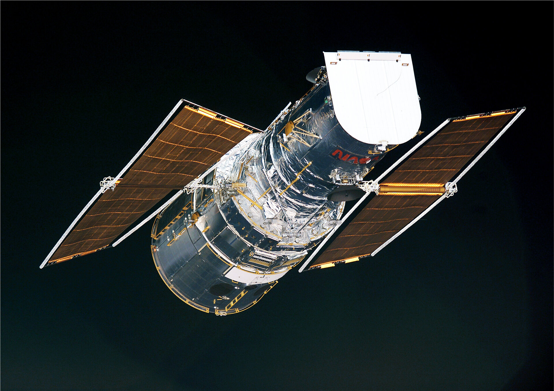
So how did ESA get its logo onto Hubble’s hull in the first place? In 1977, the same year the US Congress approved project funding, NASA and ESA made an agreement.
In what turned out to be a good bargain, the Agency gained 15% of the telescope’s observing time, and access to the complete mission data archive, in return for contributing a science instrument (the Faint Object Camera), designing and building Hubble’s solar array and providing engineering support throughout the mission’s operational life.
That latter assignment might sound like a simple-enough task. After all, just about all satellites are equipped with solar arrays, converting sunlight into their lifeblood of electric current.
But Hubble presented some very special engineering challenges. To begin with, these solar arrays needed to be taken back to Earth, afterwards. This presented a valuable technical opportunity, to find out first-hand how orbital hardware would endure orbital conditions – but the arrays would have to be very specifically designed.
2. Designing roller blinds for space
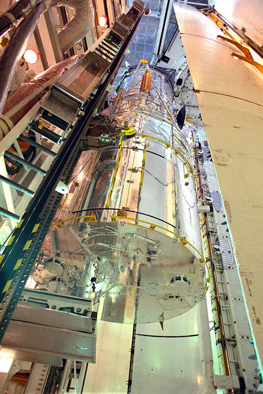
“The original plan was for the Shuttle to make maintenance visits every 2.5 years and the entire telescope to return to Earth for major overhauls every five years,” said Lothar Gerlach, ESA Project Manager for the Hubble Solar Arrays, who has been working on the project in one capacity or another for 30 years. “That was quickly dropped, but the idea of in-orbit replacements remained.”
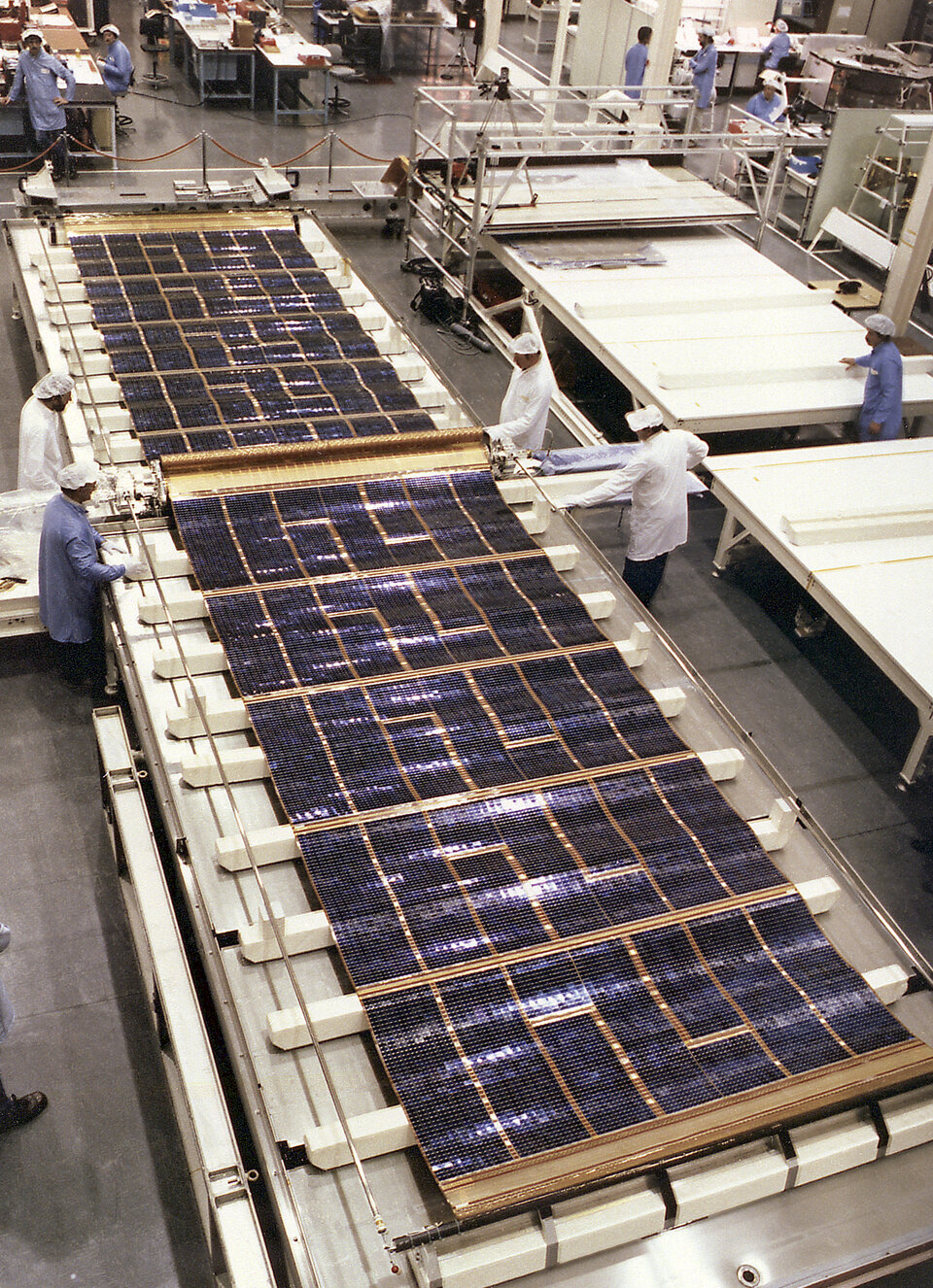
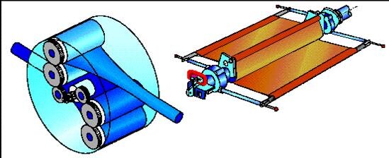
Standard missions used rigid solar arrays that unfolded in orbit, but the Hubble arrays ended up more like roller blinds, with a pair of flexible blankets covered with solar panels on each side of the satellite.
“The blankets needed to be flexible because they had to fit between the round hull of the telescope and the round Shuttle cargo bay,” added Lothar.
“We were faced with an exceptionally tough volume restriction. That meant we also needed solar cells that didn’t break when they were rolled up.
“The blankets also needed to be retractable, to be rolled back up and brought down to Earth again.”
3. Challenges of flying low
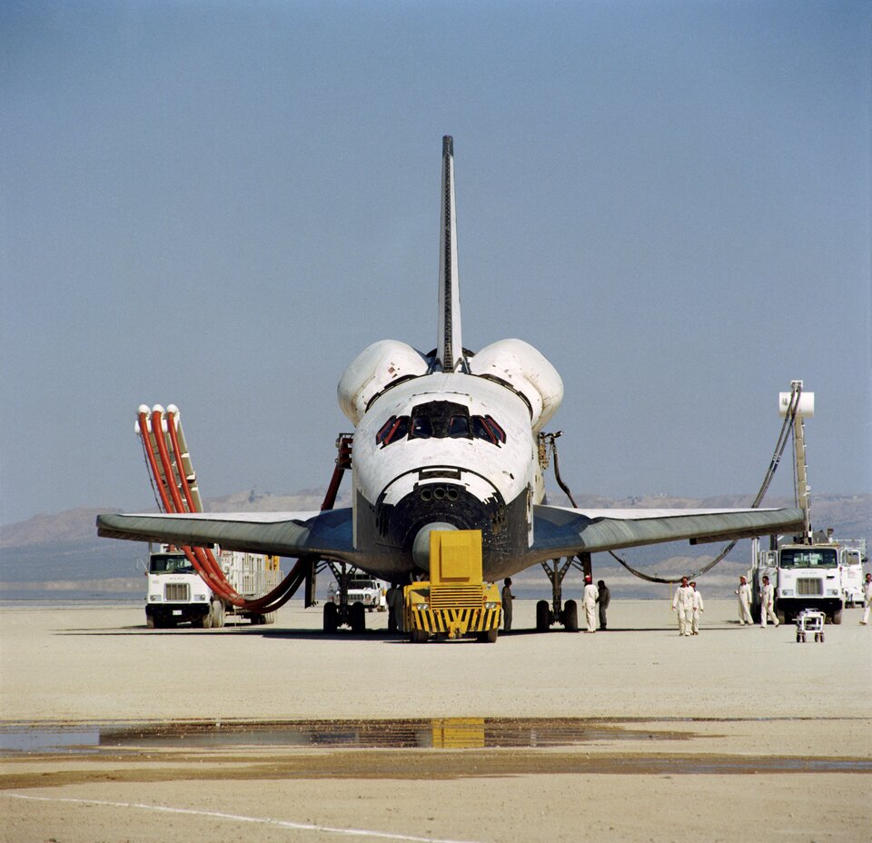
The other main challenge was Hubble’s place of operations: low orbit, around 600 km up. “It’s a very dynamic thermal environment, with the Sun rising and setting every 96 minutes,” said Lothar.
“And each time the temperatures shift from plus to minus 100ºC between sunlight and shadow.”
The arrays needed to stand up to around 30 000 thermal cycles over their five-year lifetime – a design life which in those days was an extremely ambitious target.
Imagine switching standard roller blinds between a cooker and a deep freeze 16 times a day. These environmental extremes meant that while the blankets needed to be flexible, they also had to be kept taut by special booms, to prevent thermal shock deforming them over time and compromising the functioning of the arrays, required to deliver 4 kW of power.
4. Shuttle findings put arrays back to drawing board
Two sets of solar arrays had been contracted – overseen by British Aerospace in Bristol with contractors in Germany, Switzerland and Denmark – along with their electronics and Solar Array Drive Mechanisms.
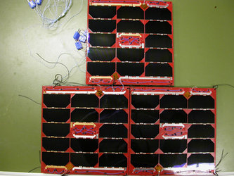
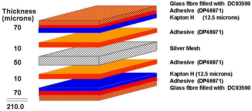
Work proceeded at the same time as the very first Space Shuttle flights, with what was then high-efficiency 12.7% silicon solar cells interconnected with silver mesh strips, which were embedded between a layer of protective Kapton material and reinforced by glass-fibre cloth.
But suddenly those same pioneering Shuttle flights sent European designers back to the drawing board.
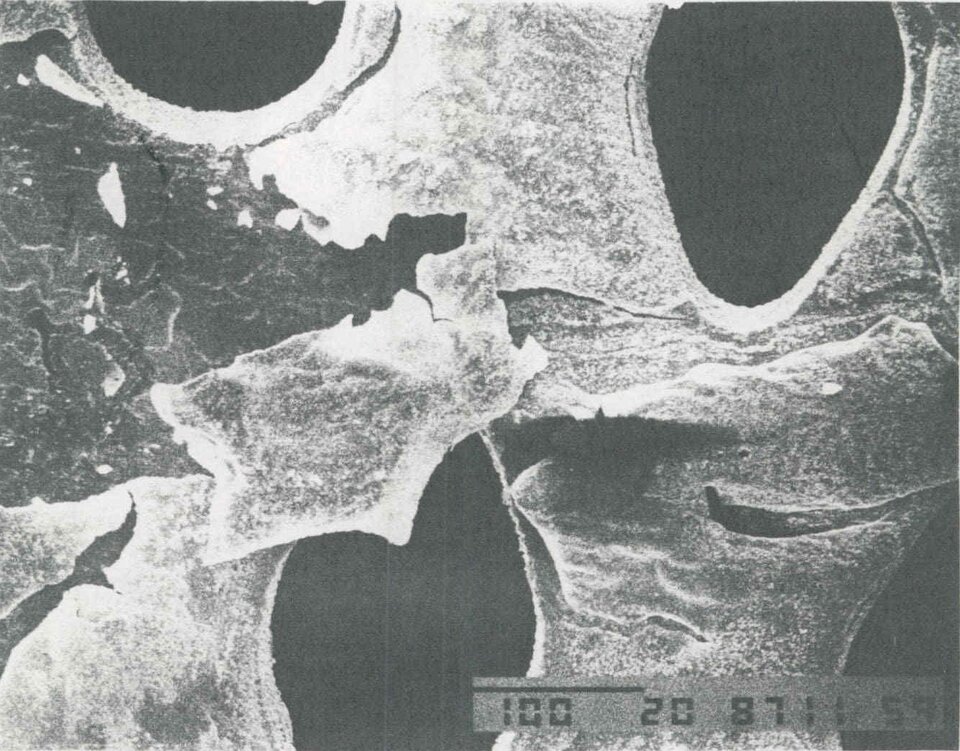
“Everybody was shocked when the first Shuttle came back with severely eroded thermal blankets,” explained Lothar. “The culprit was atomic oxygen: highly reactive, individual oxygen atoms found at the top of the atmosphere."
"We needed to find out if our design could stand up to atomic oxygen, so material samples were flown on the Shuttle flights that followed. The results were far from good.
“We’d worked so hard to find the right parameters for solar cell interconnections, only to find out that the silver and Kapton we relied on would have been eroded away completely inside a few weeks.
“There was no easy fix – we had to start again. This was the point when I first found myself working for Hubble.”
The redesigned solar blankets used molybdenum-based interconnectors, which were oxygen safe, while the Kapton was protected by a silicone coating.
On other parts of the array, such as the primary deployment arm, exposed Kapton was replaced by polytetrafluoroethylene foil. On the plus side, the designers incorporated newer 14%-efficiency solar cells into the updated design.
5. Hubble gets the shakes
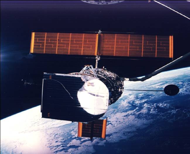
After a long delay owing to a broad range of technical and budget issues, then elongated by the 1986 Challenger disaster, the Hubble Space Telescope was finally launched on 24 April 1990.
Within a matter of weeks it became apparent that all was not well with the fledgling mission. Besides the famous ‘astigmatism’ due to a slight mirror error, the observatory experienced about 10 seconds of jitters each time it passed between night and day plus some randomly occurring disturbances caused by a failed compensator mechanism, sufficient enough to affect Hubble’s very-high angular resolution imaging.
This meant for example, that what would later became Hubble's signature long-duration ultra deep field observations would have been severely impacted, if not impossible.
“Hubble’s solar arrays were flexing every time they passed through the day-night terminator,” explained Lothar. “The disturbance torque was not really bad, but above the maximum allowable momentum of 0.007 Newton metres.
“At that time, 25 years ago, we had not had precise-enough test equipment or the size of vacuum chambers needed to verify this requirement on the ground.
“It turned out to be due to the bi-stem booms used to deploy and tension the arrays. These are made from a pair of circularised steel sheets which fit together in a C-shape to form a cylindrical boom.
“Because they were overlapping each other we expected them to basically have the same temperature, but when one side was in sunlight and one in shadow the thermal contact was poor and they expanded at differential rates, clicking against each other like little earthquakes.
“In addition, we saw a failure on one array of a compensation mechanism used to adjust for temperature-driven flexing when part of the array fell into shadow.”
| This article continues... |
|
| Next |
|


 Germany
 Austria
 Belgium
 Denmark
 Spain
Spain
 Estonia
 Finland
 France
 Greece
 Hungary
 Ireland
 Italy
Italy
 Luxembourg
 Norway
 The Netherlands
 Poland
 Portugal
 Czechia
 Romania
 United Kingdom
 Slovenia
 Sweden
 Switzerland


