Ion engine gets SMART-1 to the Moon
ESA’s SMART-1, due to end its mission on 3 September, has ably demonstrated that for interplanetary missions, replacing or augmenting chemical propulsion by using electric thrusters for the primary propulsion system can bring numerous benefits.
Thanks to the success of the SMART-1 mission, future ESA interplanetary missions such as Bepi Colombo will use electric propulsion systems as the baseline for the main primary propulsion systems. The benefits include:
- increase in net payload mass enabling missions that would otherwise be impossible
- reduction in flight time in comparison to a mission based on chemical propulsion and complex gravity assisted operations
- reduction in mission operation costs
- independence from launch window constraints imposed by the classical gravity-assisted planetary fly-by operations allowing an increase in a mission’s scientific objectives
- ability to use small/medium launch vehicles leading to savings in launch costs
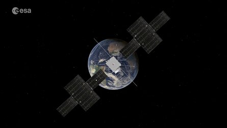
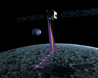
SMART-1, ESA’s first SMART (Small Missions for Advanced Research in Technology) mission, is a small lunar orbiter designed to demonstrate innovative and key technologies for scientific deep space missions.
SMART-1 was launched on a highly innovative and low budget mission to explore the Moon on 27 September 2003 by an Ariane 5 launcher from Europe’s Spaceport in Kourou, French Guiana. The orbiter successfully passed all the critical mission phases to reach moon operational orbit on 22 January 2005. It is scheduled to hit the moon’s surface on 3 September this year once it has consumed all the propellant on board.
Mission Phases

The first phase, which lasted approximately four months and used mostly continuous thrust outside eclipses, was the crossing of the radiation belts from a standard geostationary transfer orbit up to an elliptical orbit of perigee higher than 20 000 km radius. The desired perigee height was reached by the end of January 2004.
The second phase, which was a thrust interruption of 25 days to delay the apogee raising phase, reduced the duration of upcoming eclipses to below 2h15m because of the design limitations of the batteries’ capacity.
The third phase was the long Earth-escape cruise with thrust arcs around the perigee and coast arcs around the apogee. During thrust arcs, the apogee was raised while the orbital plane was rotated.
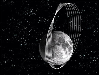
Once the apogee had been raised to a distance of 230 000 km in the middle of August, the lunar resonances phase started. The first lunar resonance took place on 19 August 2004 followed by two additional resonances carried out about 27 days apart. These served to drastically raise the perigee and rotate the orbit both in inclination and argument.
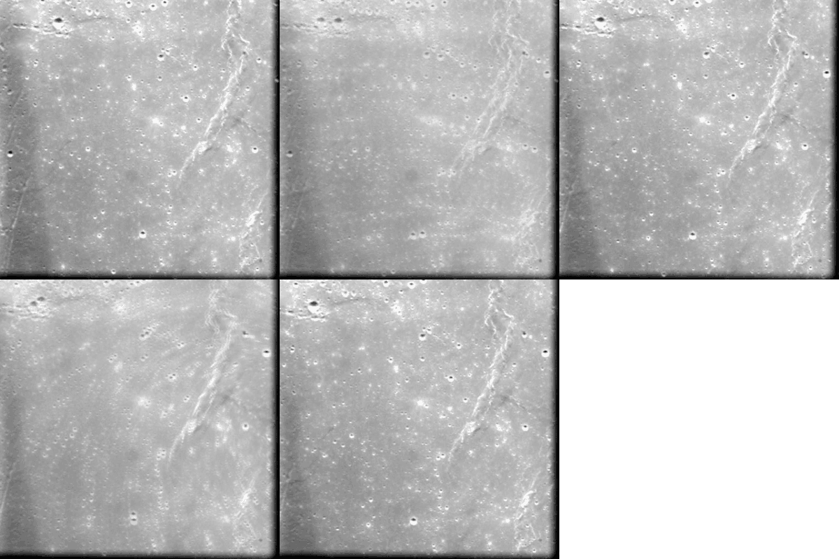
SMART-1 is the first spacecraft to follow this type of manoeuvre in combination with electric propulsion; a manoeuvre which helped to prepare successfully for lunar capture. This occurred on 15 November 2004 during a 5-day thrusting manoeuvre used in breaking mode for the first time. This mode was used around perilune during the Moon descent phase up to the final operational polar orbit of 300 x 3050 km.
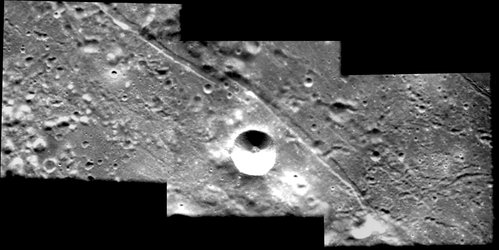
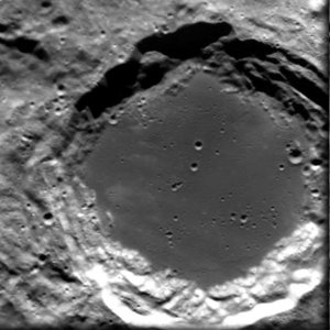
The nominal Moon observation phase lasted six months, during which the electric propulsion system remained off and approximately 8 kg of xenon remaining for use during the SMART-1 mission extension. Thanks to the efficient use of the propellant, the mission was extended to September 2006.
Electric Propulsion Subsystem

The SMART-1 Electric Propulsion Subsystem (EPS) is based on the PPS-1350-G Hall-Effect plasma thruster (SNECMA Moteurs, France), which is designed primarily for North-South Station Keeping of large geostationary satellites. On SMART-1, a small platform, the thruster, is used for primary propulsion. Therefore, some features have been implemented at subsystem level to limit peak inrush power, to operate over a large power range, to regulate electronically the xenon pressure and to use a new communication standard (CAN).
The EPS consists of three main functions:
- xenon propellant storage, distribution, pressure and mass
- flow rate regulation
- power regulation and thruster discharge supply
- digital data bus interfacing and communication
In the single central 49-litre tank, the xenon propellant (82.5 kg at launch) is stored in super critical conditions under high pressure (up to 150 bars at 50C). An electronic pressure regulator called the Bang-Bang Pressure Regulation Unit (BPRU), designed by Snecma Moteurs and Iberespacio (Spain), delivers the xenon to the Xenon Flow Controller (XFC) at a constant and settable low pressure, nominally 2 bars.
A simple and robust control-loop algorithm, stored in the Pressure Regulation Electronic Card (PRECard) built by Atermes, France, controls the constant pressure delivered by the BPRU. The XFC then controls precisely the xenon mass flow rate to the thruster anode and cathode.

The thruster is controlled and powered by the Power Processing Unit (PPU), developed by Alcatel ETCA, Belgium. All telemetry and telecommands are interfaced to the EPS through the PRECard. Commands collected by the PRECard are either immediately executed when related to the BPRU control, or transferred to the PPU. An electric filter called the filter unit, produced by EREMS, France, filters the discharge current oscillations and protects the PPU components from over voltage. Both the PRECard and PPU contain software routines with automatic modes to reduce the number of telecommands sent routinely to the EPS from the ground.
In nominal operation, the EPS has two automatic control loops active. One software loop, contained in the PRECard, regulates the xenon pressure in the low-pressure plenum tank upstream of the XFC. The PPU supplies a power-limited voltage to the anode, according to the nominal power set command, which also sets the discharge and magnet currents. The PPU then controls the thruster discharge current via the XFC thermo-throttle current in closed loop. This varies the xenon viscosity by changing its temperature, therefore varying the mass flow rate through a calibrated temperature-pressure dependence.
To cope with varying solar array power throughout the mission the EPS is designed to be easily throttled over a wide range of input powers. The nominal power set command to the PPU allows 117 different power levels to be set, ranging from 462 W up to 1190 W. The PPU also performs the automatic thruster ignition sequence, redesigned for SMART-1 to limit inrush power at ignition.
The SMART-1 EPS is mostly a single string system including only redundancy at cathode and xenon supply level in order to be single-failure tolerant for the components considered to be most sensitive. Automatic failure detection is available both internally in the EPS and in the spacecraft onboard software within the EP manager.
The excellent electric propulsion system in-flight performance, combined with the lower than expected degradation of the solar array by radiation, have increased substantially the xenon propellant margins. By using some of this extra xenon, the lunar capture date has been advanced by four months from March 2005 to November 2004. In addition, the lunar observation orbit has been lowered from 1000 x 10 000 km to 300 x 3000 km to improve the scientific return, for example in terms of cartography resolution.
An extension of the mission has also been achieved. To reach the Moon observation orbit, the thruster has produced a total delta-V of 3.5 km/s and consumed 74 kg of xenon. The cumulative operating time until today is around 5000 hours and the final Xenon consumption is 82 kg.
For more information please contact:
Giorgio Saccoccia – Head Aerothermodynamics and Propulsion Division
Giorgio.Saccoccia@esa.int
José Gonzalez del Amo – Head Electric Propulsion Section
José.Gonzalez.del.Amo@esa.int
Denis Estublier – Manager SMART-1 EP Subsystem
Denis.Estublier@esa.int


 Germany
 Austria
 Belgium
 Denmark
 Spain
Spain
 Estonia
 Finland
 France
 Greece
 Hungary
 Ireland
 Italy
Italy
 Luxembourg
 Norway
 The Netherlands
 Poland
 Portugal
 Czechia
 Romania
 United Kingdom
 Slovenia
 Sweden
 Switzerland


