Antenna Laboratory
What are their roles?
The Antenna Laboratories focus on assessing the performance of antennas, an essential element of space systems.
ESA/ESTEC operates some of the largest European test facilities dedicated (but not limited) to testing of space hardware. Among them is the Antenna Laboratory. The Antenna Laboratory, through its several facilities and over 30 years of existence, provides state-of-the-art measurement services to ESA projects and external customers and explores and develops new measurement techniques. They comprise various labs located in ESTEC, ESA and an offsite facility, the DTU-ESA Spherical Near Field Antenna Test Facility, operated by the Technical University of Denmark, provides additional services.
Between them, these facilities support testing across the entire spectrum of antenna development, from characterising the properties of candidate materials for antennas, including measurement of their RF absorption, reflectivity and dielectric properties, to assessing the performance of antenna subsystems up to the qualification validation of full-scale complex radiating systems such as a fully-integrated satellite incorporating multiple antennas aboard.
What services do they offer?

Antenna Testing
The Antenna Laboratory provides testing capabilities for antennas and payloads such as radiation pattern measurement, absolute gain, phase centre determination, group delay and any other end-to-end payload and platform radiated performance across a frequency range between a few tens [LR1] of MHz and 1.5 THz. Some of these capabilities are available under various environmental conditions, in order to verify antenna and radiated payload performance in-flight. Available facilities include the Compact Antenna Test Range (CATR), the Hybrid European RF and Antenna Test Zone (HERTZ) , the Sub-mmwave Scanner (SMS), Menlo Time Domain Spectrometer (TDS) and Low Temperature Near Field THz Chamber (LORENTZ).
RF Material Characterisation
The Microwave and (Sub)mm-wave Material RF characterisation facilities (the Scatterometer and Microwave Material Characterisation Facility) make up the Antenna Laboratory offering state-of-the-art polarimetric and coherent material characterisation services in a frequency range between 1 GHz and 1.5 THz . Capabilities available include determination of transmission and reflection losses, scattering measurements and determination of complex material properties for antenna applications such loss factor and dielectric constant under various environmental conditions.
In addition, a specific an Antenna Mesh Characterisation facility has been setup to measure mesh samples required for future large deployable reflectors (Link). There are a large number of variables that can be altered in the fabrication of such material, with each variation having a direct effect on the RF performance. Therefore, it is important that an accurate and consistent test setup is used to characterise each sample. This test setup combines a fully automated measurement process that is precisely aligned with the assistance of the Metrology department (link?). Custom software developed for the acquisition and post-processing of the data allows for full tractability of the measurement and the associated uncertainties. This results in a detailed understanding of the materials transmission, reflection and absorptions at multiple angles under linear and circular polarisation. An upgrade to this facility is in development that will allow measuring the direct correlation between the bi-axial tension of a mesh and is RF performance.
How are they equipped?

The 100.000 class cleanroom HERTZ facility combines the Compensated Compact Range (CCR) and a Near Field Range (NFR) in the same anechoic room, both dedicated to radiating antenna and payload measurements. The purpose is to verify the in-orbit performance of complex radiating systems by testing the different units forming part of the system as a whole. HERTZ is capable of offering direct far field measurements, through a plane wave zone of 5 x 5x 7 m, covering a frequency range of 3.4 – 23 GHz. The Near Field facility complements the latter through state-of-the-art capability in Planar, Cylindrical and Spherical Near field measurements between a few tens of MHz and 50 GHz. The acquired near-fields are then post processed and all required far field parameters calculated. This hybrid test aptitude is offered to antennas, payloads and full spacecraft up to 5000 Kg and 6-meter maximum dimension (depending on test requirements). For planar scanning, the test item does not need to move and can even be positioned on its own support, allowing for example, testing antenna and payload performance without removing the spacecraft from its multi purpose trolley.
The offsite DTU-ESA Spherical Near Field Antenna Test Facility offers expertise in calibration services for antenna gain standards, catering to a frequency range of 0.4 – 40 GHz, a load capacity of 250 kg and a typical gain calibration accuracy down to 0.03 dB.
The CATR is dedicated to testing small to medium sized antennas, up to 1 m diameter and 100 kg mass, in an ambient but anechoic and EM-isolated chamber across a standard frequency range of 4-110 GHz with custom-made instrumentation able to cover 110-250 GHz. The CATR incorporates two parabolic cylindrical aluminium reflectors to collimate RF signals in order to mimic the far distance of space, inside a shielded anechoic chamber with an overall size of 12.5 x 8.5 x 4.3 m. Radar measurements such as absolute reflectivity of absorber materials or Radar Cross Section (RCS) characterization are also possible.
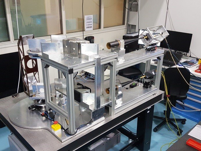
The Microwave Material RF characterisation free space test facility comprises two corrugated feeds and grids with collimating elliptical mirrors focused at the sample position. The set-up is used in conjunction with the CATR positioner. It allows polarisation measurements in transmission and reflection configuration (both monostatic and bistatic) and can accommodates sample sizes of 300x300 mm or 400x400 mm. The system is fully automated so numerous polarisation states and sample incidence angles can be measured in one run. This facility enables the characterisation of materials for antenna radomes, reflectors, electromagnetic band gap structures as well as frequency/polarisation selective surfaces (FSS). In addition, reflection measurements can be performed over a wide temperature range, up to 500°C. The pair of horns for each frequency band is either directly connected to the network analyser (8-50 GHz) or to solid state frequency extenders based on multipliers and mixers (50-110 GHz).

The (sub)millimetre-wave Quasi Optical Test Facility characterises the RF properties of space materials and antennas using three dedicated test setups.
The SMS is a precision (sub)-millimetre wave planar nearfield scanner with the purpose of measuring accurately antennas and radiated payloads operating at frequencies above 50 GHz and up to 1.5 THz. Typically used for Science and Earth observation radiometers and millimetre wave imagers, its situated in a class 100.000 clean room to comply with the necessary environmental conditions of flight hardware.
The (sub)mm-wave Scatterometer is a quasi-optical free-space RF measurement test bench that, when combined with a network analyser and dedicated analysis software, provides a powerful measurement tool for the determination of complex material properties. It allows the characterisation of dielectrics, ferrites, reflective surfaces and a variety of printed structures, such as FSS, CPSS, half-wave plates and lenses. The set-up is installed in a controlled clean room environment ensuring adequate conditions for flight hardware testing. The main advantage of this system is the possibility of measuring samples with high absorption or thickness. Co-polar and cross-polar components of the transmission and reflection properties of the samples under test can be determined by using high performance corrugated horns, grids and refocusing mirrors. In addition, a periscope-based design allows state-of-the-art measurements of the scattering proprieties of materials over a wide angular range.
The Menlo TDS system allows for the measurement and imaging of samples up to 6 THz. This increase in frequency range will be required for future Science and Earth Observations missions.
All facilities can be encased in a nitrogen tent, to remove any atmospheric effects.
The Low Temperature Near Field THz Chamber (LORENTZ), is the newest antenna test facility developed for ESA. It is unique in that it can test antennas in the frequency range of 50-1500GHz in a realistic space environment. The main vacuum anechoic chamber can accommodate instruments with a volume of 1900mm x 1900mm with a mass up to 500kg. The antenna under test can be temperature controlled from 80-390 K (-190c – 117 c) with future plans to go down to 4k (-270 c). Then through a novel design, the antenna pattern can be measured using a 1x1m planner scanner which remains at room temperature. This setup allows for the full end to end measurement of instruments in a truly representative environment.
Who are their customers?
The Antenna Laboratory provides support to both ESA projects and external customers – including small-medium-sized companies lacking access to comparable private-sector facilities – needing to assess new antenna designs and techniques and qualifying designs for flight. This has included some of ESA’s largest flight hardware.
Projects that received recent support include antenna measurements for forest monitoring mission Biomass, ongoing tests for the next generation of Galileo, as well as numerous CubeSat missions. The facility has also been greatly involved in the testing of mesh samples for large deployable reflectors.
How do I find out more?
Contact:
Laboratory Coordinator, Luis Rolo Luis.Rolo@esa.int
Head of the Antenna and Sub-mm wave Section, Peter de Maagt peter.de.maagt@esa.int,
Head of the RF Payloads and Technology Division, Piero Angeletti piero.angeletti@esa.int
For more technical details please download the brochure below.


