The Dual-stage 4-Grid (DS4G) Ion Thruster Design
The DS4G thruster consists of three subsystems namely:
- Mechanical subsystem: clamping mechanism including aluminium clamp end plates, clamp posts, and thrust balance mounting ring.
- Radiofrequency subsystem: gas injector, plasma source tube, RF 3-turn antenna, stand-off transformer, impedance matching box, RF generator.
- High Voltage subsystem: interchangeable grid module with four grids and three inter-grid spacer rings, HV vacuum feedthroughs & connectors, two HV and one LV power supplies.
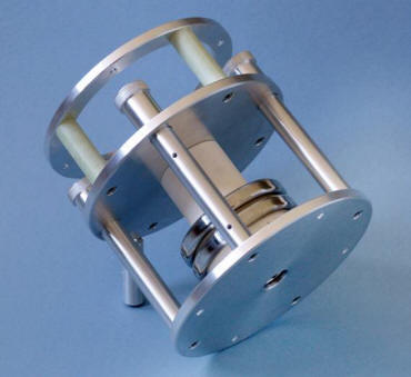
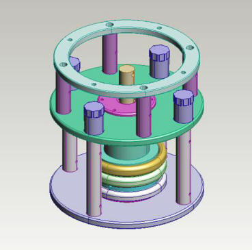
A picture and 3D CAD model of the thruster are shown in Fig. 1 and 2. The plasma source tube (white cylinder in the picture) is 5 cm inner diameter, the beam diameter is 2.3 cm and the clamp plates are 20 cm in diameter. The total mass is 5 kg, but the design has not been mass optimised since it is only a laboratory model intended to rapid interchange of electrode layouts during the test campaign. A spacecraft engineering model would weigh less than 1 kg.
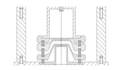
The plasma source tube contains high density Xenon plasma during RF discharge and is connected directly to the HV electrode module (see Fig. 3 for the 2D design drawing). The first grid (top in the drawing), called the plasma grid, interfaces with the plasma in the source tube and is at the highest voltage of up to 30 kV to create a high beam potential. The second grid, called the extraction grid, is at a lower voltage to to create a potential of <5 kV to safely extract ions from the source tube without excessive beamlet divergence and grid impingement problems. The third grid, called the acceleration grid, is at a low slightly negative voltage in order to really accelerate the extracted ions through a high potential electric field and prevent external electrons (e.g. from secondaries produced from the ion beam hitting the test chamber 's graphite target, or from a hollow cathode neutraliser on a spacecraft) from backstreaming into the thruster. The fourth grid, called the ground grid, interfaces with the clamp plate and is at ground to isolate the thruster from erosive charge-exchange ions created in the beam.
In addition to the thruster, ancilliary equipment were also obtained by ESA in order to support the test. This included:
- Two FuG 35 kV high voltage power supplies from Air Parts BV (80 mA current rating).
- 1 kW RF generator from MKS (13.56 MHz).
- 1 mass flow controller from Bronkhorst (0.002 - 0.14 mg/s).
- Single Langmuir probe from Alta to supplement existing diagnostic tools.
Typical, operating voltages for the grids are:
- Plasma grid: +30 kV
- Extraction grid: +27 kV
- Accel grid: -0.4 kV
- Ground grid: 0 kV