The DS4G Test Diaries: Week 1 (by Christina Bramanti)
Tuesday, 2nd May 2006
The test team unpacked the grid optics from its shipping crate and started to assemble the DS4G (Double Stage 4 Grid) thruster in its first configuration for performing the 1st phase of the experimental tests.
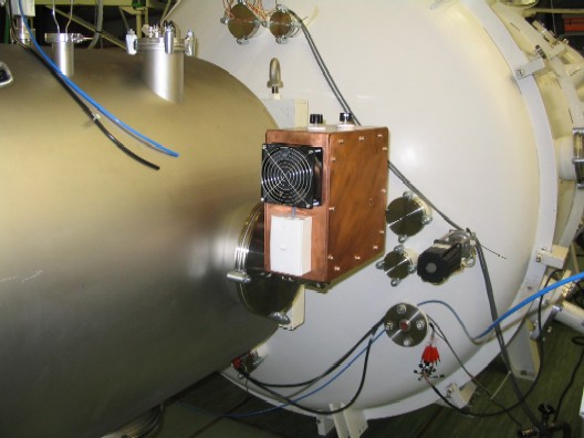
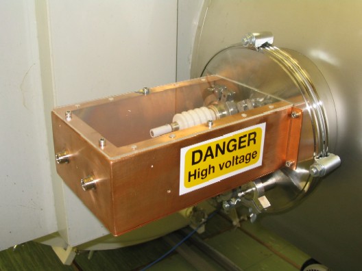
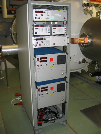
Then, our work was mainly concerned with installing the RF supsystem into the CORONA hatch, setting up the Xenon gas flow system and calibrating pressure with mass flow rate from the controller. Here you can see the RF impedance matching network box, to be used for tuning the RF for inducing the Xenon plasma discharge and obtaining a complete absorption of the RF power by the plasma for maintaining a high plasma density in the source tube.
In the meanwhile we started to assemble the ACT diagnostics (Faraday Cup, Langmuir probe and calorimeter), specifically designed for characterizing the high energetic DS4G beam.
Wednesday, 3rd May 2006
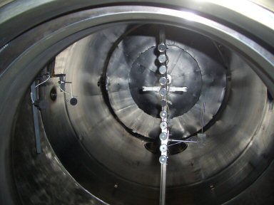
The whole day was dedicated to finishing assembly of the ACT diagnostics outside the chamber and installing them inside the main chamber.
We mounted the Faraday cup on the dedicated arm inside the chamber and performed a laser alignment of the thruster bore-sight with the diagnostics tools by working inside the main chamber.
In the meanwhile in the CORONA hatch....
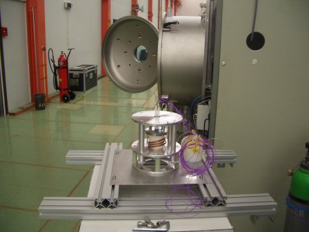
....we loaded the DS4G; we mounted the high voltage supsystem with vertical mount, feedthrough, cables and electrode connectors and thermocouples attached to the top and bottom clamp plates, gas injector and 1st grid (only for this 1st phase as no voltage will be applied) for temperature monitoring.
Thursday, 4th May 2006
Today was a really busy day at CORONA and we worked hard to install all of the remaining diagnostics equipment, Langmuir probe and calorimeter, on the dedicated arm inside the chamber and performed a laser alignment of the thruster bore-sight with the diagnostics equipment by working inside the main chamber.
All the electrical interfaces were connected and verified. So we are ready to go to vacuum.
We closed the gate between the main chamber and the CORONA hatch and we started the vacuum procedure of the main chamber in the late evening.
Friday, 5th May 2006
In the morning we checked that all the electrical interfaces inside the CORONA hatch and the approval from a ESA technical expert was provided.
We started up the vacuum turbo-pump of the CORONA hatch...
On Monday we will be ready to start the first experimental tests!!!!!!!!!!!!
Coming up next week:
- 1st phase experimental campaign: plasma characterisation inside the source tube.
- 2nd phase experimental campaign: HV breakdown tests up to 30 kV with the new grid optics to increase the thrust and the overall efficiency of the DS4G thruster.