Nanokhod
In the frame of future exploratory missions within the solar system there is a need to extend the range of scientific measurements from the immediate vicinity of static landing stations to a wider radius of a few tens of meters.
Instruments or sensor heads can be deployed by a small vehicle or rover, thus acting as an ‘extended robotic arm’, while maximizing the mass allocation for scientific equipment.
Even with this limited mobility it becomes possible to expand the investigated area by several orders of magnitude compared to the capabilities of a purely lander-mounted payload.
The Nanokhod microrover was embraced by ESA in the course of the “Micro-robots for Scientific Applications” activity as the most promising realisation of an ‘instrument deployment device’.
The activity, funded by ESA under a TRP contract, has been carried out by a consortium of companies and research institutes led by Von Hoerner & Sulger GmbH, Germany.
Nanokhod main design features

The rover is designed so that the scientific sensor instruments can be accomodated in the central payload cab.
The locomotion is performed by means of tracks. The locomotion system is able to position the payload cab with 2 Degrees of Freedom.
The rover power and data connection to the lander is implemented through thin tether wires.
The rover control and navigation is semi-autonomous: it exploits a 3D digital elevation model of the terrain, aquired by means of panoramic camera on lander.
The thermal control is entirely passive while the electrical power peak consumption is 3 W.
The total Payload mass is 1100 g. The rover mass without P/L is 1450 g.
Breadboard model

A first model breadboard of the Nanokhod was realised with the aim to:
- demonstrate performance of locomotion and payload positioning;
- be representative for mass and volume of the Flight Model;
- host payload dummies (represented as mass);
- operate autonomously for at least 1 hour;
- be built to laboratory breadboard quality level;
- be operated and demonstrated easily in different test bed environments (inside, outside);
- be operated with its own remote control station over a distance of 20 m;

The fidelity of the breadboard with respect to a flight hardware configuration is summarized in the following table:
| Functionality | Breadboard Implementation |
|---|---|
| Payload Accomodation | Mass Only |
| Structure and Locomotion |
locomotion functionality. environmental compatibility only in proof-of-concept tests |
| Electrical Power |
tether concept and power electronics tether unit for 50 m travel distance |
| Telecommunication | Tether concept |
| Control and data handling |
no P/L functionality 8051-class micro-controller automated piloting sequences |
| Thermal control | passive, not for Martian conditions |
| Lander segment | Power and communication interface only |
| Control | Simple computer based MMI for direct control. Ground segment is out of scope |
Tether for power and telecommunication
The Nanokhod gets its power from the lander that delivers it on the planetary surface.
Also all telecommunication from/to the rover/the lander is conveyed through the tether.
The tether is paid out by the rover during its motion. The tether in the breadboard had trhe following characteristics:
- 2 wires, 30 sub-wires each, spliced into 15 sub-wires each;
- transformer arrangement provides two redundant half-duplex serial links, 19200 bps.
Nanokhod Breadboard Performances
The Nanokhod was subject to a test campaign to evaluate / verify model performance with respect to locomotion and payload positioning. More specifically the following features were tested:
- traction capabilities on soil simulant;
- tether dynamics (tether deployment while driving);
- slope climbing;
- overcoming of obstacles;
- recovery from tip-over situations;
- payload cab positioning;
- turn on the spot and move backwards;
- control and sensors;
- Driving on Flat Terrain performances:
- total travel distance: 20 m;
- 33 minutes non-stop operation;
- effective travel speed: 36 m/h;
- flawless tether deployment;
- slope climbing performances:
- max. angle: 24° (required: 15° upwards/sideways, 20° downwards);
- obstacles: 10 cm height / width (ideal step / trench) ;
End-to-End Control Strategy
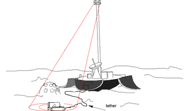
Additional equipment envisaged to support the control and navigation of the rover:
- an imaging head placed on top of the lander and fitted with optical means to allow modelling of the environment and the localisation of the Nanokhod (part of Lander System)
- a lander-mounted computer that runs the navigation software and controls the rover through the tether (part of Lander System)
- a ground control station (Ground Segment)
The "Interactive Autonomy Control Mode" is used. This has 3 phases of operation:
PRE-PREPARATION: starts immediately after the lander settles on the planet surface. The relevant elements of the control system are used to acquire the characteristics of the environment in which the rover will operate. In particular the geometry of the terrain is acquired with the use of the imaging head and high precision Computer Vision algorithms. Computer vision is also used to classify local soil characteristics (e.g. sand, gravel. hard-rock)
- PREPARATION: in this phase rover operations are programmed. The rover motion and interaction with the environment is planned, programmed in form of rover programs and verified. In particular this entails:
- Selection of target points by scientist
- Ordering and optimisation of target points in a mission
- Mission decomposition in navigation commands
- Path planning of navigation
- Path decomposition in trajectories (trajectory planning)
Trajectory verification through simulation
- UTILISATION: In this phase the rover programs are downloaded to the Lander Control System and executed. This phase includes also the analysis of the telemetry produced during the execution. A lander control system measures continuously the rover motion by means of the imaging head together with some localisation software. The control system is therefore able to correct deviations from the planned trajectory before they become significant.
The complete end-to-end control chain has been implemented in the activity “Payload Support for Planetary Exploration” (PSPE) with the imaging head produced in the “Micro-mechanisms and camera adaptation” (PlanetMicroCam) activity.
Towards an Engineering Model
The development of the Nanokhod has been continued in the “Robot technology for Planetary Exploration“ (RTPE) and in the “Mercury Robotic Payload” (MRP) activities, allowing the Nanokhod to reach the engineering model level of qualification.
REFERENCES
- European Tracked Micro-rover for Planetary Surface Operation, R. Bertrand et al, ASTRA’98, ESTEC (NL), 1-3 Dec. 1998 Design and Control of an Innovative Micro-Rover, M. Lauria et al, ASTRA’98, ESTEC (NL), 1-3 Dec. 1998
- The Lunar Rover Mockup of ESTEC’s Planetary Utilization Testbed, M. Van Winnendael et al, ASTRA’98, ESTEC (NL), 1-3 Dec. 1998
- Autonomous Vision-based navigation of the Nanokhod rover, B.Steinmetz, K. Arbter, B. Brunner, K. Landzettel, 6th International Symposium on Artificial Intelligence and Robotics & Automation in Space i-SAIRAS 2001, Canadian Space Agency, St-Hubert, Quebec, Canada, June 18-22, 2001.
- Nanokhod – A MICRO-ROVER TO EXPLORE THE SURFACE OF MERCURY, R. Bertrand, J. Brückner, M. van Winnendael, 6th International Symposium on Artificial Intelligence and Robotics & Automation in Space: i-SAIRAS 2001, Canadian Space Agency, St-Hubert, Quebec, Canada, June 18-22, 2001.
- Microrover Design for Extreme Environments, R. Bertrand, M. van Winnendael, 7th ESA Workshop on Advanced Space Technologies for Robotics and Automation 'ASTRA 2002' ESTEC, Noordwijk, The Netherlands, November 19 - 21, 2002
- Monitoring and Control of a Tethered Micro-Rover for Planetary Exploration:Results and Lessons Learned, L. Steinicke, B. Fontaine, G. Visentin, 7th ESA Workshop on Advanced Space Technologies for Robotics and Automation 'ASTRA 2002' ESTEC, Noordwijk, The Netherlands, November 19 - 21, 2002


 Germany
 Austria
 Belgium
 Denmark
 Spain
Spain
 Estonia
 Finland
 France
 Greece
 Hungary
 Ireland
 Italy
Italy
 Luxembourg
 Norway
 The Netherlands
 Poland
 Portugal
 Czechia
 Romania
 United Kingdom
 Slovenia
 Sweden
 Switzerland


